CG3000 ATU Woes! Part 1

I noticed that my last posting was in May 2025, this did not mean I was idle at this QTH. Both Mike (M0AWS) and Steve (M0XVT) kept asking when I was going to update my site as I had various projects on the go!!

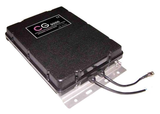
I as usual was operating HF happily in the evening and closed the station down as usual, however the next day in the afternoon when I went to operate my station again I found the CG3000 unresponsive (Relay Click was not present!) when I powered it via the control box that it was supplied with when bought at ML&S.

Usual checks was then followed to see if there was a power supply issue using my multimeter. I confirmed power was present at the ATU end so this issue was with the device itself.

I placed a call with ML&S and spoke to Gary (Workshop) regarding my problem. I needed to send the ATU back to them. My decision was to drive to ML&S with faulty ATU and handover for repair.. I also asked Mike (M0AWS) if he wanted to come along as he lives only 3 Miles away and he agreed and offered to drive as he wanted to drop off his FTDX10 he was selling. Well 2.5Hrs drive from Suffolk, we arrived at their site.

I duly handed the unit over and then we had a discussion on whether this was still covered under warranty and was happy that they confirmed this was.
We spent sometime looking at the various offerings whilst there and as always enjoyed a coffee that was offered to us.. I also bought a HH.. Blog to come on that.

The next day after dropping the ATU for repair, I received a call from ML&S (Gary) who informed me that it was fixed and was on it’s way back to me via DHL. The cause was a faulty plug-in chip (PD8255A Programmable Peripheral Interface) that was duly replaced and Gary tested that the ATU was fully operational and tuned a wire in their workshop.


Within three-days I received a fully operational ATU back at my QTH with the offending faulty chip. My thanks to all the team at ML&S for such a quick turnaround.

I was back in action on the HF bands again a very happy chappie..

Further blog on what possibly was the cause of the ATU defect in Part 2…..
AllStarLink Node Build

Well I had read the excellent article from Mike (M0AWS). Venturing into the world of AllStarLink . This prompted myself to build this project as it was a good idea when propagation is poor to be able to still keep in touch with like minded Hams.

Now I will not go into detail of the build as this has been covered very well by Mike, however I will add my observations on how I got to the stage of a working system. My first step was to order the various parts required for the build as follows:

Please note: I have since found out that I should have ordered the PSU @ 5 Amp not 3 Amp. This can be purchase from Pimoroni, you will also need a convertor plug to power the 3B Plus. USB-C to Micro-USB Adapter (I have yet to order this myself as using the original PSU for now).

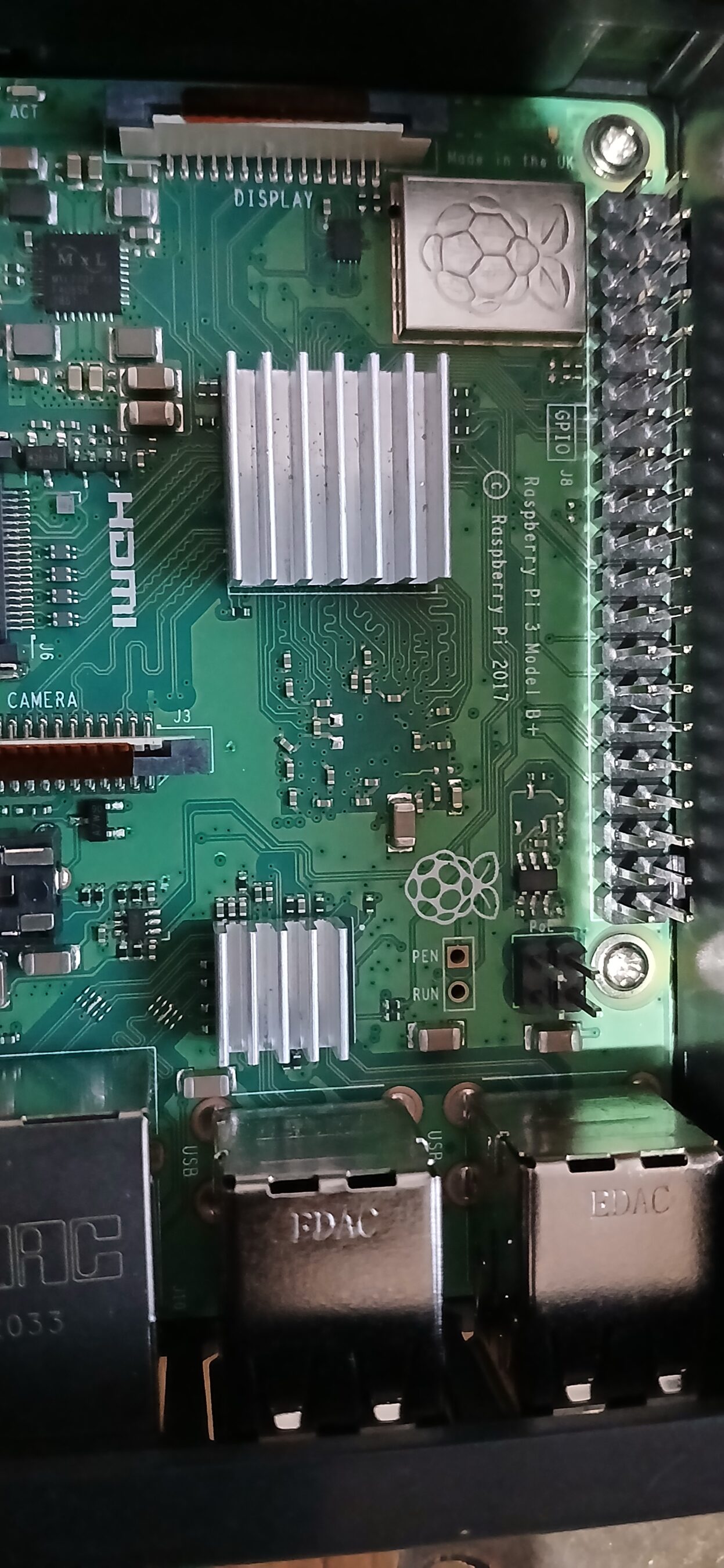
I must confess that I have dipped my toe into the waters of a Raspberry Pi. whilst I have used all forms of hardware over my decades of working in IT (Retired), this is my first SBC system of this type. It comes in kit form so I needed to ensure the heat-sinks were fitted correctly.

I also wanted to check before starting that it worked! After it was all put together I connected the HDMI and power cable and switched on……OK a red light appeared! on the board but nothing from the display. Quick internet search revealed no onboard BIOS. You need the OS installed on the SD card first….sorted 🙂

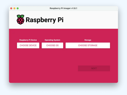
The next task was to install an OS to the SD card. I used the Raspberry Pi Imager, this was already available in Kubuntu 24.04 as a resource. Once I had it installed, I placed the SD card in my laptop and you just select the OS.

I went for a simple OS install Debian 64bit with KDE Plasma build just to check that the PI was functioning correctly. This was confirmed so I then continued with the excellent build instructions from Mike (M0AWS) as follows:

Automated Raspberry Pi/SHARI Node Build

Just follow this concise instruction. I must as Mike points out, to ensure you do this first. “Before you run the script make sure you have your node number and node secret to hand. These are obtained from the AllStarLink portal. “

Once this was done, I had a fully working system and was able to connect to my node here at my QTH. Further tests with Mike (M0AWS) and Steve (M0XVT) confirmed it was working, however they both informed me of a serious mains hum from me. This was identified by the PSU that came with the PI set.

To confirm this, I connected my Shari Node to my rig external PSU and set this to 5V DC output. I had no mains hum reported. PI PSU binned!, I did cut the output lead that powers the PI as this was needed for the test. Now as my external PSU is for powering the rigs, I needed a way to provide power from a 13.6V to 5V. I sourced the following:

DollaTek Small DC Buck Voltage Converter Step Down Voltage Regulator Module Board 4-38V to 1.25-36V 5V/12V Adjustable Output Voltage Stabilizer Transformer

This product provided 5V needed to power the Node. I did have an issue of getting the required 5V output but you just need to turn the small screw anticlockwise quite few times! I used my multimeter to confirm the 5V output before connecting the PI power.

The final part to this build was to have the node announcement give the call signs rather than a number, so back to Mike (M0AWS) for that part as follows:

Add Node Names to SHARI AllstarLink Announcements

More to come……

Adieu Windows 10/11

I have used many versions of Microsoft Windows over it’s lifespan. I will not go into detail of the past versions!, as they have been well and truly documented in fine articles on the web.

I will only explain why, at long last, ditching Windows OS for good at this QTH , also the reasons why? The preparation that was required for me to transition to Linux.

When Microsoft decided that your PC hardware had to be of a certain build level to allow upgrade to Windows 11 from version 10, I saw a ‘Red’ mist descending over me. Looking at my various existing equipment of; Two Laptops, Three PC’s all running Windows 10 just fine. All of the above hardware was of reasonable spec to!

I was already using various software to run, ‘Virtual OS’ for testing in a Windows environment. The two that I used:-

  • Oracle VirtualBox
  • VMware Player

Now my first task was to look at the, Windows 10 system I used for my existing shack PC to connect to the Radio and what current software I was using at that time. I also checked content of the following folders:- Download, Music, Pictures and Documents. Note:- Good time to clear out superfluous files to reclaim disk space! Once this was done, I next looked at the current software being used as follows:

  • WSJTX
  • GridTracker
  • Log4OM

Now as I was planning to move over to a Linux OS (Kubuntu 24.10 “Oracular Oriole” with KDE Plasma Desktop), I needed to check what software could be installed to have a similar setup to the Windows environment. (Well nearly!)

Last but not least, once I was happy that all was backed up to my local NAS system including my log book of calls, I started the process of Virtualising the physical PC as this hardware was going to have Linux installed and would wipe the whole hard-disk capacity. I did not want a duel boot OS system!

Virtualisation of the PC hardware was done using VMware Convertor Stand-alone. This was installed on the target PC and run as the local administrator, this allowed me to have a fully working image of my PC. I tested this by using the, VMware Player and ensured the image started and the apps I used worked fine.

Now at the time of writing this, I have found that the VMware Stand-alone Convertor is not available to download since Broadcom acquisition of VMware products. There does appear to be another product, however I have not tested this as of yet. Here are the details if you want to investigate at your own risk! to evaluate the software. Ensure you check the site for content integrity. Search for:-

StarWind V2V Converter and P2V Migrator As a Hypervisor Switch

More to come……

CG-3000R Remote Auto Tuner Long Wire 1.8 – 30 MHz

I decided it was time to get a proper auto ATU for my EFHW 160-10M Multi-Band Aerial.

The article on Mike (M0AWS) website regarding this ATU being used with his EFHW that my aerial was derived from gave me hope that this was the way forward.

I duly ordered from ML&S the CG-3000R, this was delivered in a few days to my door.

I removed my FC 20 ATU and replaced with the new CG-3000R and duly connected the EFHW to the connector and tightened the wing nut. Ensured a good ground earth to the ATU with the ground radials connected. Now all that was needed is to connect the remote box cable to the ATU and provide power to the control box. It was nice to hear a click from the CG-3000R on power up and red light on control box. The last but important part was to connect the radio to the RF input of the ATU which has a SO-239 connector.

Operation is pretty straight-forward, you just apply 10W carrier with tone and after the chattering dies down in the ATU the remote box displays a green light. SWR came back at 1:1 on the FTDX10 display for the 60M band, so I was well happy.

My only gripe with this setup is to ensure you only tune up with 10W, no more! This ensures you do not damage the ATU. The FTDX10 has no low carrier power tone function to do tuning at present. I just set the Mode to AM with RF Power at 10W then key up till ATU tuned. Once this has been done I can then increase the power.

Note: I do this tuning for each band as whilst the ATU is powered it uses it’s memory to store your band selections. Once I change Bands you just get a click rather than chattering on first tune-up.

The only thing you have to be aware of is where you operate in each band as the ATU could tune again if SWR rises owing to frequency change in the chosen band section.

So what was the SWR for each band after connecting to my Multi-Band Inverted L. please note that the readings have been taken on the spot frequency for FT8 only, except for the Top Band where I used SSB. I will in due course provide a detailed graph for each band segment for this section.

  • 160M SWR 1.2:1
  • 80M SWR 1:1
  • 60M SWR 1:1
  • 40M SWR 1:1
  • 30M SWR 1:1
  • 20M SWR 1:1
  • 17M SWR 1:1
  • 15M SWR 1:1
  • 12M SWR 1:1
  • 10M SWR 1:1

Multiband Vertical Inverted L

Hindsight is a great way to think outside the box! The aerial has been up a few months but there was a few issues still to contend with as follows:

  • Vertical Pole sections collapsing.
  • Change the fixings to the workshop side panel.
  • AWG of wire used.

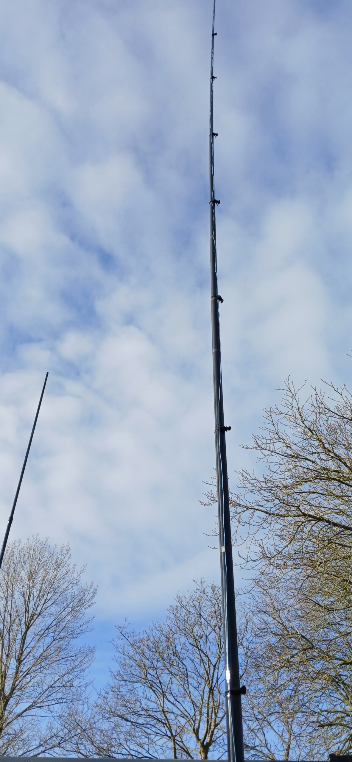
Vertical Pole sections collapsing. I had at first tried normal large cable ties to provide a firm grip to each tube section to keep sections from collapsing….This did not work! I needed something!! Rather than using metal clamps which can damage sections if over-tighten, I happen to chat with Mike(M0AWS) on this subject and he provided me with a link to DX Commander Website of usable clamps which use a key or hex nut to tighten on their poles which works very well on my Spider Pole. https://dxcommander.com/product/50mm-diameter-ezyclamp-for-dx-commander-wing-nut/#iLightbox[product-gallery]/1 Please note that this link is for the 50mm which I used to fix the tube sections from collapsing, the top three sections are secured by tape as the diameter of the tubes are too small for the clamps.

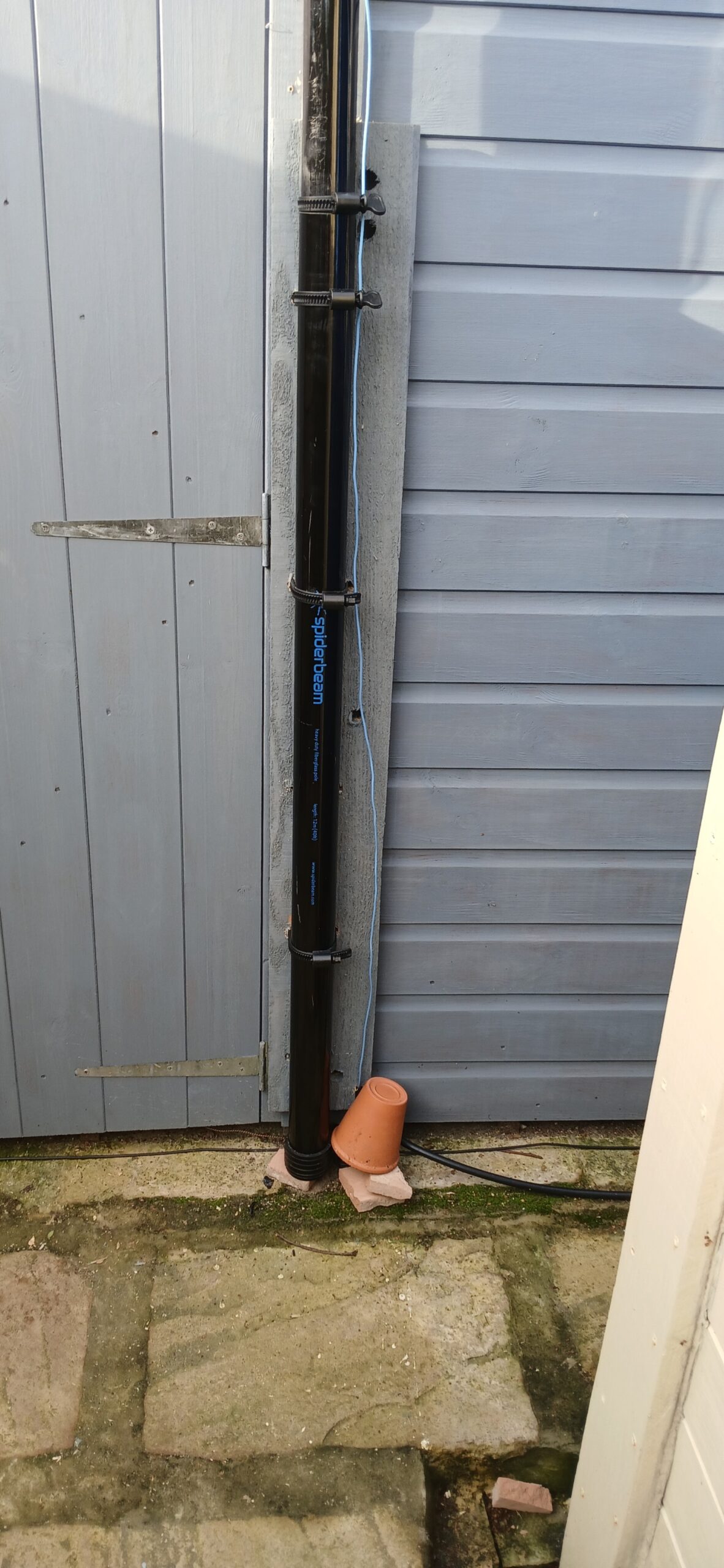
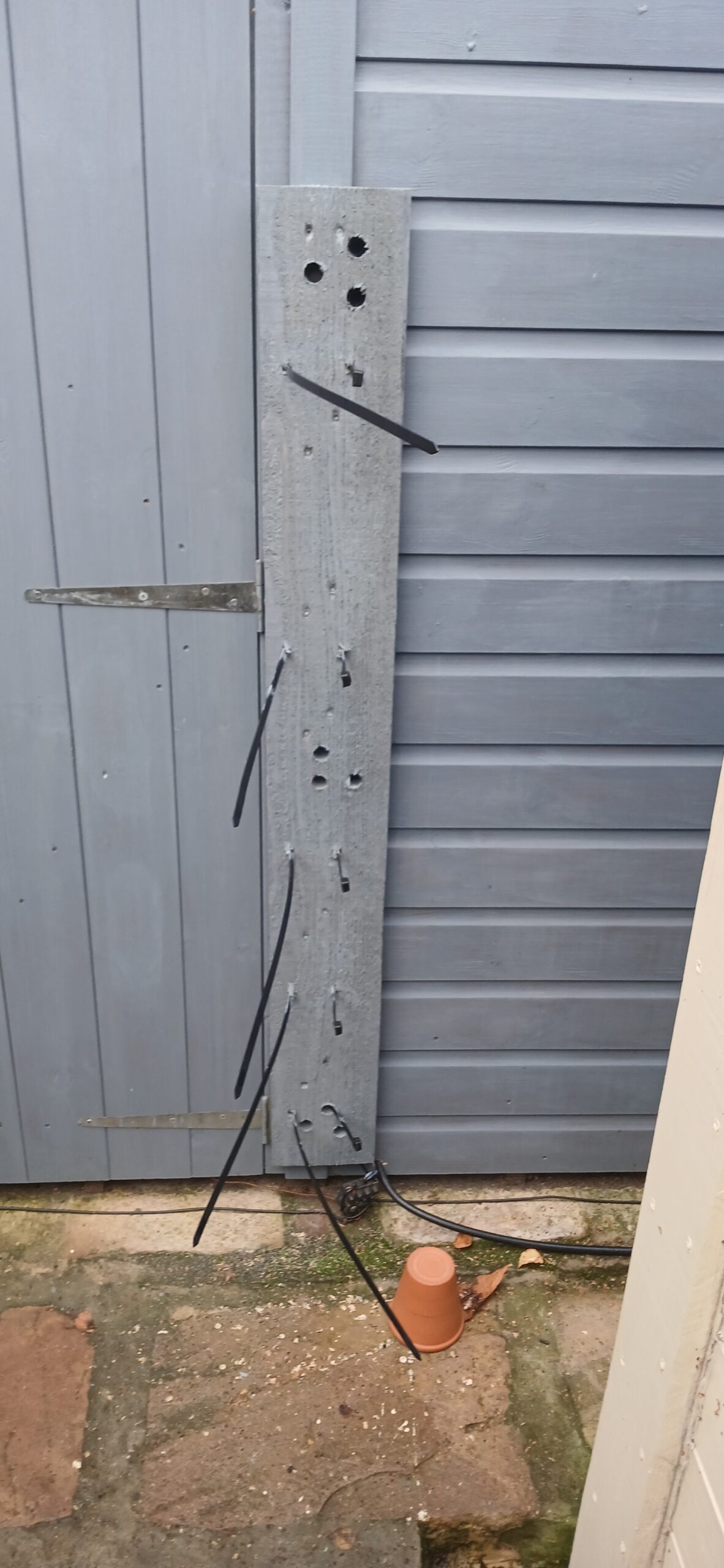
Change the fixings to the workshop side panel. I also used their 75mm with hex nut rather than key x 4 to fix base pole tube to workshop as shown in picture on the left , this to allow easy maintenance of the pole. Note that the flower pot upturned is to cover the choc-block connector for the radials to ground earth until I get a proper waterproof case to replace pot!

AWG of wire used.

When the new aerial was first erected, I used a very thin insulated copper wire (AWG 23) that Mike (M0AWS) kindly supplied me. This was used for the full run of 106Ft, this was fine but as the vertical pole would collapse, the fine wire would then get ensnared inside the tube sections which caused them to jam-up!

Once I had taken apart the poles to remove the wire, I decided that a 1mm insulated wire (Blue Wire in above picture) would run up the pole from the ATU and at the top of the aerial , I allowed a further 2ft bent at 90 Degrees so that I could then attach by soldering the thin wire to this for the run down the garden to the Cottage end. The use of a fine wire was to ensure that there was not too much loading and also blend in with the surroundings.

From an environmental perspective, I also attached tiny bits of tape on the wire slope to ensure our flying wildlife around here did not get en-snared in the wire.

The adjustable clamps work extremely well. I collapse the vertical pole when the wind strength becomes excessive. All that is left up is the three top sections which I have used tape to fix in position.

More to come…

ATU Yaesu FC 20.

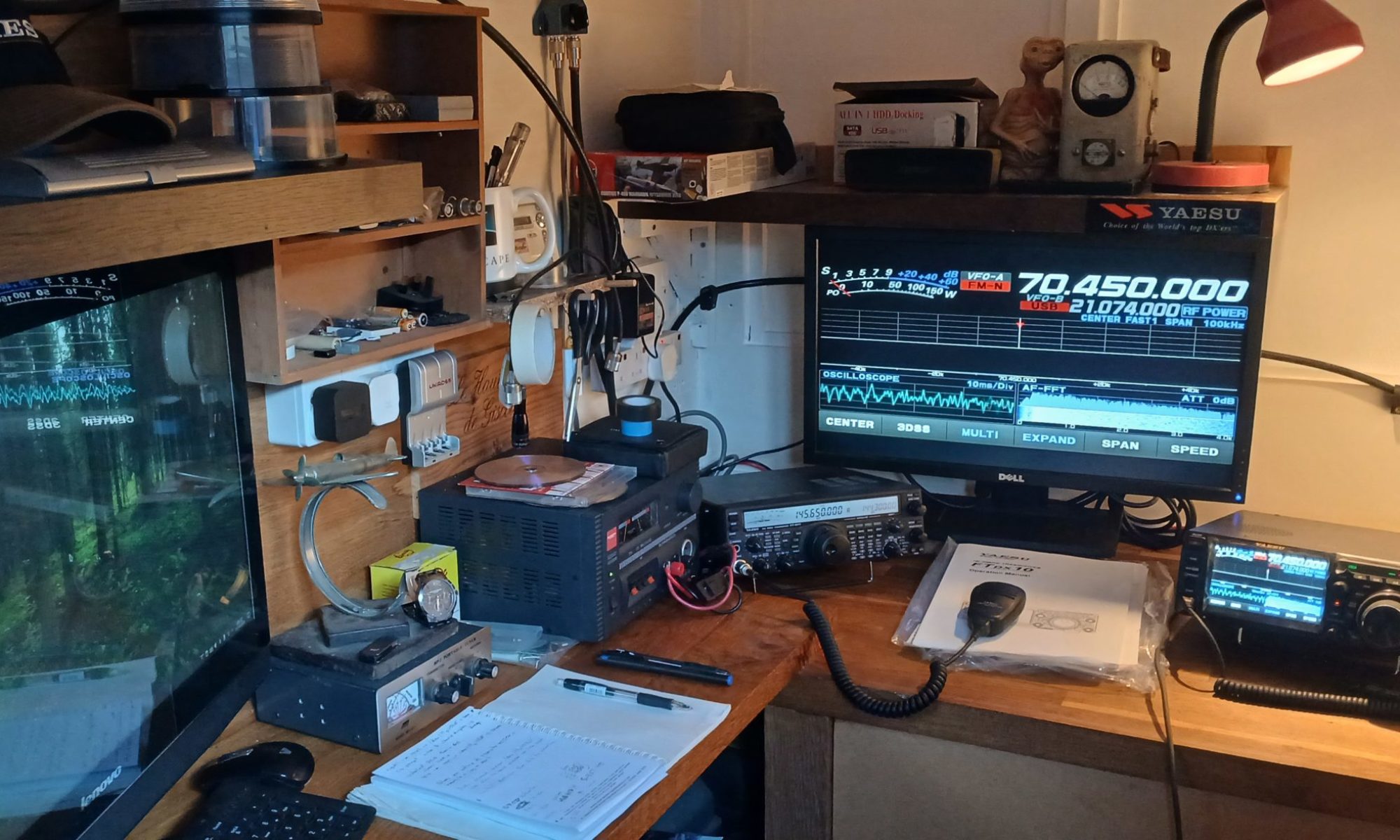
Whilst I had a nice radio in the shack, I looked at the schematics of the FTDX10 and FC 20. Looking at the data cable pin out/in, I noticed that they were the same. I made a control cable of 15Ft as I had placed the FC 20 at the other end of the workshop to where my vertical was fitted outside by the door. Using an 49:1 unun to my end fed aerial.

Setting the FTDX10 to use the EXT Tuner, when I tried to tune up on the band, I could hear the FC 20 trying to match. I found that the radio found it was hard to get the SWR low. (I know the FC 20 was used with my FT847!).

I had to revert to my MFJ-971 Portable Tuner to allow me to use the new radio in the short term on the bands. This had a deep null when tuning and made setting up each band awkward.

I did try to use the FTDX10 internal tuner but again could not get SWR low enough for the EFHW Multi-band Inverted L

More to come……

Build Phase Continues….

I was keen to get the vertical pole fitted to the workshop side panel. I used large tie wraps to achieve this and had the bottom section securely fixed via a wood plank which I drilled holes through as seen in the picture. (Note! Ensure you have the top section up a little to get hold of when you start to extend pole sections. I used tape to keep it slightly extended.)

The next part was to attach the wire to the top section using tape. I then raised each section in turn which involves some arm muscle to twist to lock each section, wire was then taped at each section until fully raised.

The design of this aerial was an inverted sloping L which was 40ft up then sloping down to a 6ft fence post next to the house, I used a large insulator as a counterbalance to keep the wire reasonably taught when vertical would sway about. I then had a total length of 106ft for the ATU. Mike (M0AWS) checked the resonance of this aerial before it was connected to the FC 20 ATU and at that time was acceptable! I connected three radials for the ATU at ground level and run them along our garden fence. Each radial was about 60ft in length.

More to come……

New Year

Hello and welcome to this site. I had to at last add some entry as a new resolution for this year. Many thanks to Mike M0AWS for hosting this site and many gentle prodding to add some content!

I have been out of this hobby for many years (20+), but in 2018, I unpacked my Yaesu Ft847, FC 20 ATU + Cushcraft R-6000 vertical which had been damaged over many location moves over the years. I mainly operated for many years on just 2 Mtrs with a Diamond 2 / 70Cms vertical when I moved to Suffolk in 2014. Chatting to various local hams in around the QTH of Bredfield, however this was using my portable FT817.

I would say my interest piqued in Ham Operation again when I met Mike (M0AWS) as we worked together in IT at my last job before I retired…just before COVID hit our shores in the UK.

I started to look at various data modes and soon had FT8 working on the FT 847 using a PC running Windows 10 using the PC Audio in/out to the Data in/out of the FT 847. I used the software WSJTX with Gridtracker and Log4om at that time which all worked very well on all bands on low power of 20W.

I then decided that as my interest increased in the hobby it was time to look at everything to do with radio and IT and how it was all going to work/fit in the new workshop/shack that I was building in an 18ft x 4ft unit. My visit to Mike (M0AWS) shack helped me formulate a plan of action on the next phase of how I wanted to move forward in my later years of retirement.

First phase was to look at what radio would fit my needs now as my 847 is long in years and bands had changed in use over this time which the FT 847 did not cover. Mike suggested we took a trip to Martin Lynch and Sons which we did at the end of June 2024 which is a good 2.5hrs drive from Suffolk. I was like a young child in a toy store looking at all the equipment on display and being able to try out what was on offer.

My main concern is I have to use hearing aids for the top frequency loss I suffer but was I impressed with the Yaesu FTDX10 HF/6m transceiver for audio clarity and the Receive filters…well WOW. How radios have improved over the years!

Now I was at the stage of a new radio, I will also require an aerial that would be fit for purpose. Once again I relied on Mike experience with various aerials he has used over his operational years as a ham. He showed me his telescopic vertical of 12M which he uses for DX and is documented on his site M0AWS which is well worth a visit for insightful information on all to do with our hobby. So my next purchase was a SPIDER-BEAM – 12m HD FIBREGLASS TELESCOPIC POLE from Waters and Stanton. Mike came round to my QTH to help setup and test with his Nano VNA which was of great help. I am going to leave this section now as there was a lot more to do and requires a further blog on the next stage of setup.

More to come……